Start with a transport question
For industrial engineers and logistics planners, an early AMR concept is more useful when it describes a specific material handoff. Which pickup and delivery points need to connect? Which transfers use the same aisle? What changes when loading takes longer?
AGVCanvas lets you arrange facilities, connect routes, and assign pickup and delivery tasks to vehicles. Use a run to explain the concept and identify assumptions worth checking on site. This example is not a validated capacity study.
An assembly flow from receiving to dispatch
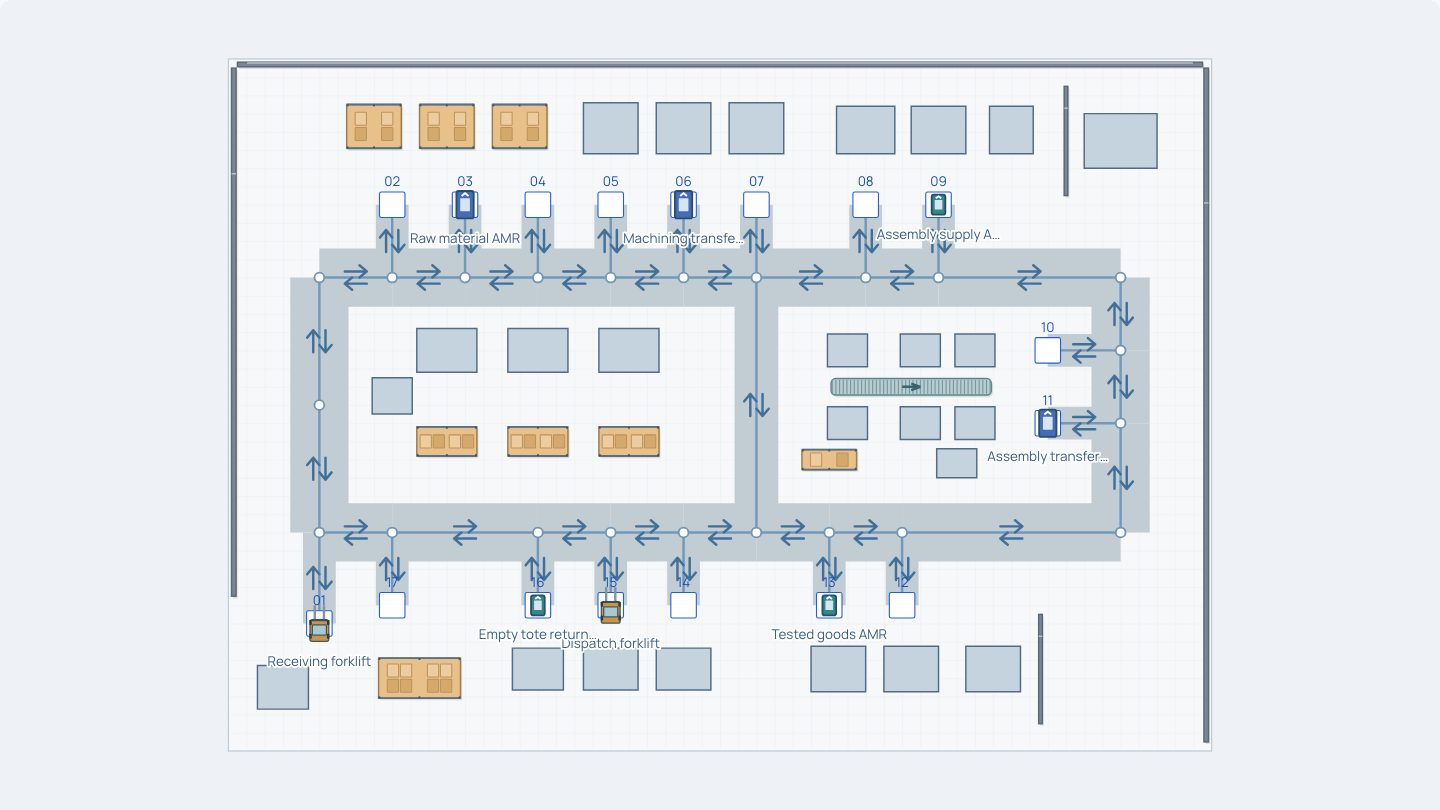
The editable example is an electromechanical assembly workshop with 6 AMRs and 2 forklifts, 9 transport tasks, and 17 stations. Vehicle roles and task assignments are already configured, so you can begin with a connected layout.
- Receiving and replenishment. A receiving forklift transfers incoming pallets to raw-material storage. A raw-material AMR supplies two machining cells.
- Work-in-process transfers. AMRs move machined parts to cleaning, cleaned parts to assembly, and assemblies to functional testing.
- Packing, dispatch and return. Another AMR carries tested goods to packing; a dispatch forklift moves packed pallets to shipping. An AMR returns empty totes to the line-side supermarket.
These are transport handoffs. Machining, cleaning, assembly and testing equipment provide context; their production cycles are not simulated as an interconnected manufacturing process.
Open, edit and run the example
Open the factory layout
Choose Open the editable factory example. The initial project is named “Electromechanical assembly · Receiving to dispatch.” If the editor restores an earlier guest draft, keep it if you still need it. Use Restore original example only when you are ready to replace the local draft with the example.
Inspect one vehicle and its task
Select a vehicle in the 2D layout, such as the Raw material AMR. Review its pickup station, delivery destination, loading and unloading times, and pickup interval in the property panel. English control names are used here; the editor follows your saved language preference.
Change one assumption
Record the original value of Loading time (s) for one task, then increase it by a few seconds. Keep the layout, vehicle speed and other task settings unchanged. A single change makes the next comparison easier to interpret.
Run and look for waiting
Choose Start presentation. Watch the simulation clock, completed transport tasks and travel distance. Pause to inspect vehicle states; use 2D to follow routes and 3D to explain the spatial arrangement. Loading, unloading and traffic waits have different causes, so check the vehicle details before treating every stop as a route problem.
Return to editing and compare
Choose Stop and return to editor, restore the original loading time, and run again. Compare both runs at the same simulated elapsed time with the same initial conditions. Use Reset presentation to restart a run. Save or export when you want to keep or share your work; those actions require signing in and follow your account’s access rules.
Turn observations into a useful discussion
A longer loading time can keep a vehicle occupied and shift its later trips. A shared aisle can cause traffic waiting even when pickup and delivery points look well separated. Follow the affected vehicle and neighboring routes rather than judging the layout from a single completed-task count.
- Check whether the planned material handoffs and return paths are easy for the team to explain.
- Note where vehicles wait, their states, and which assumptions could explain the delay.
- Compare completed tasks and distance over an equal run duration; these describe this model, not your plant’s proven output.
- Record the route or timing change and the next site measurement needed to check it.
Model assumptions and engineering limits
- Illustrative layout and inputs
- The built-in geometry, vehicle dimensions, speeds, task intervals and handling times are synthetic inputs. Replace them with measured site data before drawing engineering conclusions.
- Fixed vehicle-task assignments
- Tasks are assigned to particular vehicles. The example does not optimize fleet size or reproduce a vendor’s dispatching system. Scheduled trips defer while a vehicle is busy; they do not accumulate a production backlog.
- Route-based transport
- Vehicles move on configured paths and follow the model’s traffic rules. A visual run does not certify clearance, braking, pedestrian interaction or safe operation. Check physical aisles, loads, turning behavior and the supplier’s requirements separately.
- Transport rather than a complete factory
- The scene does not establish production capacity, equipment reliability, demand variability or your WMS/MES behavior. The example has no live equipment connection and does not control robots.
Use the result to communicate an early concept and prepare questions for detailed simulation, equipment suppliers and on-site engineering validation. Confirm operational and safety requirements before implementing a real system.
Try one change in the factory
Start with a transport task you can explain. Change one input, run again, and bring the observations back to your team.
Open the editable factory example